
The NRTF is the premier DoD outdoor facility for Radar Cross Section (RCS) testing. It specializes in narrowband and wideband RCS signature characterization of scaled, full-scale and flyable articles. Additionally, it provides characterization data for antenna radiation patterns and antenna backscatter. Due to its remoteness and secure environment, the NRTF can accommodate customers requiring specialized testing of developmental systems. In addition, it provides unmatched full-service range support, rapid-response test preparation, design, conduct, data collection and processing. As a T&E leader, the NRTF maintains RCS dominance through teamwork, expansion into new technologies, constant improvements and first-class customer service.
NRTF History
Beginning in 1963, the NRTF began measuring radar scattering at the Radar Target Scatter (RATSCAT) site and then later expanded operations to the RATSCAT Advanced Measurement Systems (RAMS) site in 1984. Since then the NRTF has successfully provided valid RCS data for hundreds of test programs. These test programs have resulted in major contributions to weapon airframe technology programs, such as the B-2, AMRAAM, F-16, F-22, F-117 as well as numerous rotorcraft and various other advanced technology programs.
Assigned to the 704th Test Group, the NRTF is located on White Sands Missile Range, N.M. and after the closure of RATSCAT now slowly operates at the RAMS site. It has provided timely, accurate, secure and cost-effective static RCS and antenna pattern measurements for the DoD and low observable community, creating the foremost test and evaluation capability at a single location for outdoor ranges.
NRTF Capabilities
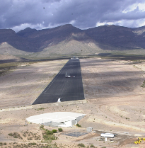
RAMS is a self-contained secure test complex. It consists of an 8,900 foot long by 300 foot wide paved, shadowed-plane range. Monostatic RCS measurements of targets up to 70 feet in length can be accomplished. The target support pylon can be extended to 56 feet above the projected ground plane and retracted into a silo for visual security. It can accommodate targets up to 20,000 pounds.
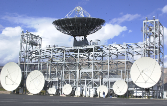
RAMS Coherent Measurement System (RCMS) is used to make precise monostatic RCS measurements on a wide variety of aerospace and ground based targets. It covers a frequency range from 600 MHz to 18 GHz and 34-36 GHz. The different modes of operation include narrowband RCS measurements, radar imaging and other diagnostic radar measurements.
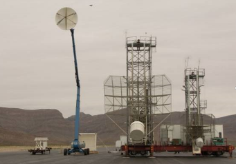
RAMS VHF/UHF Measurement System (RVUMS) is a mobile radar system that optimizes low frequency measurements. It covers a range of 120 MHz to 600 MHz and is usable over a range of 1,500 to 2,500 feet from the target. It is a pulsed, monostatic measurement system that has the capability to collect full scattering matrix data in both bands simultaneously over 480 MHz bandwidth. The antennas adjust for height to establish a balanced field illumination across the target aperture for any frequencies within the band of each antenna.
Signature Analysis Bases Editing Reconstruction (SABER). RCS measurements suffer from many types of additive and multiplicative errors due to environmental factors and equipment instabilities. SABER is a computer based tool used to separate these errors from the target return. It utilizes basis pursuit methods for signal recovery by separating additive contamination in RCS imagery and identifying optimal models for band gap interpolation.
NRTF Upgrades
ReDI Range - The Research, Diagnostic and Integration Range is a 2,000 foot scaled range that provides that capability to enable parallel operations with the NRTF's main range during customer testing and downtime for maintenance cycles. Scheduled maintenance cycles dominate the downtime between tests; thus, making it extremely difficult to conduct experimental or integration type work. The ReDI range will provide a scaled range capability to enable research, diagnostic and integration work independent of the main range.
ARMR - Advanced RCS Metrology Radar system is a radar upgrade and improvement program designed to meet current and future metrology requirements by incorporating the capability to transmit multiple frequency bands simultaneously; thus, improving efficiency and data throughput. Also, improving Ku and X-band sensitivity by a factor of three. Utilizing critical expert analysis signal processing which will provide efficient data parsing and quality analysis. Finally, incorporating a modular design to increase MTTF and MTTR.
Pit 6 - This project will install a rotating table into a target pit and integrate it into the command and control systems at RAMS, capable of testing non-penetrable/full-scale targets weighing up to 60k pounds and greater than 40 feet wide.
Ku-Band Sensitivity Project - The purpose of this project is to improve the sensitivity of the Ku and X-band capability at RAMS by adding a second antenna, transmitter and waveguides, as well as removing the transmit, receive and polarization fast switches. Also purchasing three X-band transmitters and one Ku-band transmitter.
VHF Calibration and Verification Horn - Research and development of the necessary calibration and verification VHF horn device(s) to support existing and potential low frequency capabilities.
| Director of Operations |
575-572-0652 |
DSN 572-0652 |
| Commander |
575-572-0651 |
DSN 572-0651 |
| Technical Director |
575-572-0653 |
DSN 572-0653 |
| Program Management |
575-687-1008 |
DSN 572-1008 |