The 704th Test Group Operating Location (704TG/OL-AA) at White Sands Missile Range, New Mexico provides co-located Test and Evaluation (T&E) support for Directed Energy (DE) technology currently under development at the Air Force Research Laboratory Directed Energy (AFRL/RD) Directorate.
Activated June 2006, the 704 TG/OL-AA focuses on developing test concepts, planning, methodology, procedures, and techniques for emerging DE programs. The 704 TG/OL-AA serves as a bridge between Research and Development (R&D) and the Test and Evaluation (T&E) community. It can directly support DE technology still under development while accelerating the transition of DE technology from R&D systems to acquisition ready programs. The T&E engineers work in conjunction with AFRL/RD scientists to better understand system capabilities, providing critical requirements for long term T&E infrastructure planning.
The 704TG/OL-AA does not actively manage a test facility. The T&E engineers utilize all available resources within the test community across all military services. This allows the T&E engineers to recommend the appropriate test resources that best suit the test objectives of any DE program.
704 TG/OL-AA supports both High Power Microwaves (HPM) and High Energy Lasers (HEL) technology.
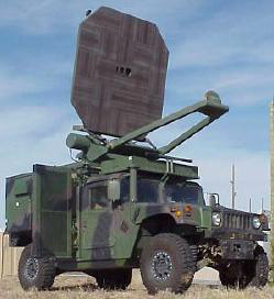
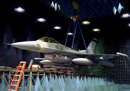
HPM Active Denial System
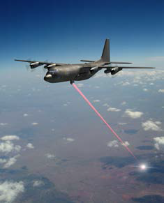
Advanced Tactical Laser
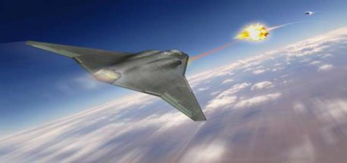
Self-Protect High Energy Laser Demonstrator Concept
Contacts:
Director (505-846-0837)
T&E Engineer (505-853-8029)
T&E Engineer (505-846-8653)
704 TG/OL-AA Directed Energy

Uses
- Embedded developmental test and evaluation personnel in AFRL's Directed Energy (DE) Directorate.
- Supports Air Force DE priorities.
- Regional DE test support through the White Sands Missile Range Test Team.
Unique Capabilities
- Joint DE test site.
- Ideal geographical location and environment.
- Extensive and specialized test infrastructure.
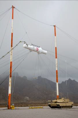
- Aerial cable site.
- Suburban test environment.
- Holloman's High Speed Test Track.
Developmental test and evaluation (DT&E) personnel are embedded in DoD's Center of Excellence for Directed Energy (DE) -- AFRL's Directed Energy Directorate.
- Provides in-house T&E liaison support to Major Range & Test Facility Base (MRTFB)
- Increases T&E awareness of DE technology.
- Provides test support to AFRL/RD programs.
Supports Air Force DE Priorities
- OSD's DE Test S&T Program.
- DE Technology Transition Council.
- AFMC's DE T&E Consortium.
- Test Planning and Execution


Regional DE Test Support through WSMR Test Team
- Army's WASMR and HELSTF.
- Navy's NAVSEA Port Hueneme White Sands Detachment.
- Air Force's 704th Test Group.
- Army Research Laboratory.
- Air Force Research Laboratory Directed Energy Directorate (AFRL/RD)

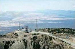
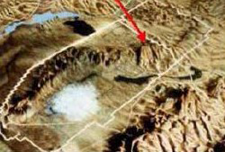
Salinas Peak High Altitude Test Site
- Mid-northern WSMR point 9,000 feet MSL.
- 360º azimuth field of view.
- Elevations of 3,500-4,000 ft. AGL.
- Salinas Peak is a major instrumented WSMR telemetry and communications site.
- Surface to unlimited airspace.
- Ideal to conduct passive, active or lethal test against airborne targets.
- Ideal for locating ground-based targets in the valley floor.
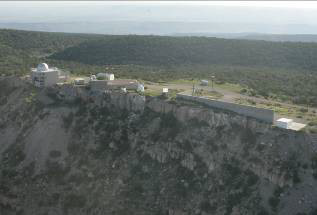
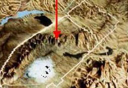
North Oscura Peak High Altitude Test Site
- Azimuth Field of view 360º.
- Look down angle into valley below -- for ground targets 3-35 miles.
- Restricted unlimited altitude airspace -- for airborne targets up to 120 miles.
- Elevations of 2,500-3,000 ft. AGL.
- Up to 4 test site locations.
- Plenty of power and communications.
- Existing facilities.
Why Test with WSMRs Test Team?
- Ideal geographical location and environment.
- Extensive and specialized test infrastructure.
- State-of-the-art WSMR control center.
- Joint DE Test Site.
- Aerial Cable Site.
- Holloman's High Speed Test Track.
- Suburban test environment at Playas, New Mexico.
- AFRL/RD - DoD's Center of Excellence for DE - Premier DE M&S capability - HEL and HPM infrastructure
- ARL - Electromagnetic Vulnerability Assessment Facility
Point of Contact
Directed Energy
505-853-8029 / DSN 263-8029